Considering the RL series circuit shown in Figure 1, and assuming that the DC power supply is E and the current that flows through the circuit after t seconds is I, the following formula holds true.
$$E=RI+L\frac{dI}{dt}\hspace{50pt}(1)$$
Let’s consider how to solve a differential equation using the Laplace transform to find the current I.
Laplace transform is expressed by the following formula. (t>0, s is a complex number)
$$F(s)=\int_{0}^{\infty}e^{-st}f(t)dt$$
$$\mathcal{L}f(t)=F(s)$$
In electrical circuits, the Laplace transform is used to transform the original differential equation into the domain of complex numbers s, then the solution is found in the domain of s, and the solution is returned to the domain of t using the inverse Laplace transform. Find the solution. It has the advantage of being easier to calculate than solving differential equations normally.
However, there is no need to calculate this integral each time, and it can be easily calculated using the Laplace transform and inverse transform formulas that are known in advance.
Now, in the circuit of Figure 1
$$E=RI+L\frac{dI}{dt}=f(t)\hspace{50pt}(2)$$
The Laplace transform of f(t) is
$$\mathcal{L}f(t)=I(s)$$
When both sides of equation (2) are transformed into Laplace,
$$\frac{1}{s}E=RI(s)+L\{sI(s)-I(0)\}\hspace{50pt}(3)$$
Since the current I(0)=0 at t=0, equation (3) is
$$\frac{1}{s}E=RI(s)+LsI(s)\hspace{50pt}(4)$$
$$I(s)=\frac{E}{(R+Ls)s}\hspace{70pt}$$
$$=\frac{\frac{E}{L}}{(\frac{R}{L}+s)s}\hspace{50pt}(5)$$
Here, in order to facilitate the Laplace inverse transformation, equation (5) is transformed by partial fraction decomposition. now,
$$I(s)=\frac{\frac{E}{L}}{(\frac{R}{L}+s)s}=\frac{a}{\frac{R}{L}+s}+\frac{b}{s}\hspace{50pt}(6)$$
Then
$$\frac{\frac{E}{L}}{(\frac{R}{L}+s)s}=\frac{as+b(\frac{R}{L}+s)}{(\frac{R}{L}+s)s}\hspace{50pt}(7)$$
In order for equation (7) to hold true,
$$\frac{E}{L}=as+b(\frac{R}{L}+s)\hspace{50pt}(8)$$
Transforming equation (8),
$$\frac{E}{L}=as+b\frac{R}{L}+bs$$
$$\frac{E}{L}=(a+b)s+b\frac{R}{L}$$
In order for this formula to hold true,
$$a+b=0,\hspace{10pt}b\frac{R}{L}=\frac{E}{L}\hspace{50pt}(9)$$
From equation (9)
$$a=-\frac{E}{R},\hspace{10pt}b=\frac{E}{R}$$
Substituting a and b obtained here into equation (6) gives us
$$I(s)=\frac{-\frac{E}{R}}{\frac{R}{L}+s}+\frac{\frac{E}{R}}{s}\hspace{50pt}$$
$$=\frac{E}{R}\frac{1}{s}-\frac{E}{R}\frac{1}{{s-(-\frac{R}{L})}}\hspace{50pt}(10)$$
From the Laplace inverse transform formula
$$\mathcal{L^{-1}}\frac{1}{s}=1,\hspace{10pt}\mathcal{L^{-1}}\frac{1}{s-a}=e^{at}$$
Therefore, equation (10) is
$$\mathcal{L^{-1}}I(s)=\frac{E}{R}-\frac{E}{R}e^{-\frac{R}{L}t}\hspace{50pt}(11)$$
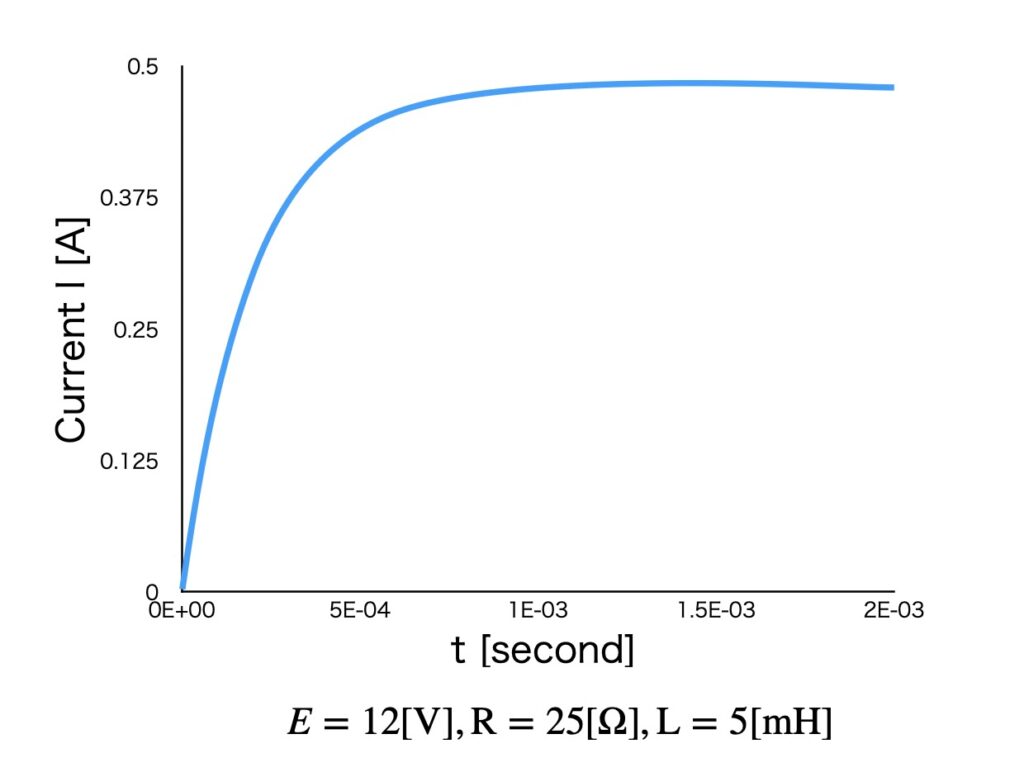
On the right side of equation (11), the first term is the current value that flows in a steady state, and the second term is the transient current value that flows in the minute moment when the power is turned on. The second term becomes 0 when t→∞.

fig.2 Transient phenomena in RL series circuit
